Your cart is currently empty!
How to use the diagnostic connector
—
by
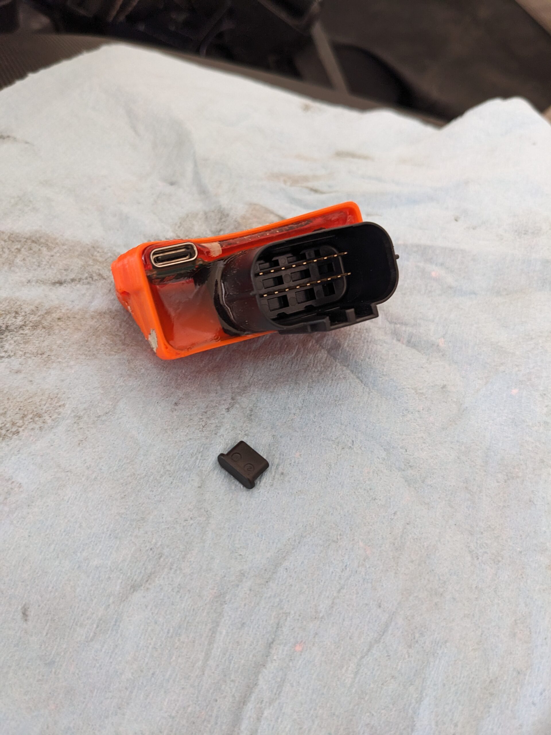
This guide will show you how to use the USB-C connector on our Veridian Cruise modules. The connector allows you to do real time diagnostics and diagnose problems on installation.
You will need:
- Android Phone, Tablet OR laptop of any make. iOS not supported due to a lack of serial terminal.
- USB Serial terminal app. I like this app but there are many options. For windows user there is PUTTY or TeraTerm.
- USB-C cable
Steps to connect:
- Install serial app
- Remove dust cover on control module
- Turn bike ignition on
- Connect device
Android Serial Term
For user with the Serial USB Terminal Android App ensure you click the connect button on the top bar

To diagnose a faulty cruise control you can enable the debug message by sending debug command.


__
PUTTY for Windows
Use the windows device manager to find the COM port Number. Here we can see the COM port is #9

Then we need to configure PUTTY as follows
Connection Type: Serial
Host Name: COM port from above. “COM9” in this case.
Lastly we also need to enable Local Echo under Terminal settings.

Click Open, type commands and enter to send.
Debug errors
For debugging the following codes will be output
RPM – RPM is below the minimum required for cruise
Speed – Speed is below the minimum required for cruise
Gear – Cruise is only enabled for gears above 1
Brake – Brake lever is being pressed
Clutch – Clutch lever is being pressed
Messages about CANBUS or CAN Age would indicator a faulty module or disconnect diagnostic connector.
Advanced commands
For more advanced functions you can also input the following commands.
| Function | Arguments | Comments |
| DFU | none | Enter bootloader mode for firmware upgrades. Will drop out of DFU with power cycle |
| config | none | Print out the current config |
| stopcode | none | Prints the last stop code from Cruise Cancel event. See Kill Conditions. Memory lost on power. |
| debug | none | Start/Stop printing Debug messages. While cruise is active: 3 data fields are: cruiseSetPoint, CAN_Rear_Wheel, output_throttle. Use for custom tuning PID. |
| reset | none | Reset Config |
| help | none | Print Help |
| wheelx | 18 | Adjust the wheel speed sensor factor. Change for custom applications or extreme tire changes. |
| speedINC | 03 | Adjust the amount to increase speed with a single press of the INC/DESC buttons. Units are KM/H |
| PID | 120 05 00 | Adjust the PID gain |
| tmax | 50 | Adjust the Maximum throttle limit. Units are 1% |
| TPSidle | none | Set the throttle input idle position |
| TPSopen | none | Set the throttle input open position |
Firmware Updates
Firmware updates are available as we tweak settings and add new features.
Check our google drive here for the latest version. Currenlty firmware updates are only supported on windows machines.
- Extract the Zip file and run the VCUpdater.bat file
- Select the desired firmware to update with a number key
- Select the device Com Port by entering only the number portion. For COM8, simply enter 8, then enter.
- Script will now put the device in Device Firmware Update mode, DFU, and attempt to flash. DO NOT DISCONNECT.
- Successful flashing will look like this.
If unsuccessful, please get in touch with your error message or see tips below. Device can be safely removed and will return to normal operation.

LIB_USB_ERROR_NOT_SUPPORTED

If you get this error, the drivers for DFU mode are not setup correctly. Leave the device connected and powered on. DFU device needs to have WinUSB Drivers.
- Download Zadig driver tool (Also included in our Firmware Zip files)
- Run the Batch firmware update script to get the LIB_USB_ERROR. Do not unplug the device.
- From the Options Menu of Zadig, Select “List all device”
- Find the STM32 Bootloader in the dropdown and change the driver to WinUSB
- Click Upgrade or Replace driver.
- Run the firmware update tool again. Any Port number can be entered.


Leave a Reply